Background
The TopoDOT® application offers the capability to import calibrated images and map the image pixel orientation to the perspective view of the selected MicroStationTM view. This unique tool makes it possible to overlay extracted CAD elements over the image in the selected view with very high precision thereby employing this image information as a reference in feature identification.
TopoDOT® places specific requirements on the calibrated image if this feature is to be successfully employed. These requirements can be summarized briefly as:
- Camera/Lens model (unique to each camera/lens pair for best results)
- Camera Location (project coordinates for each image)
- Camera Orientation (defined with respect to project reference frame)
The responsibility for providing the tools necessary to extract this information lies with the system manufacturer. The operator should follow manufacturer’s process procedures necessary to acquire this data efficiently and accurately.
Certainty 3D will cooperate with any manufacturer to import their specific file formats. As increasing numbers of manufacturers add such calibrated image capability to their systems or individual operators attempt to develop their own solutions, Certainty 3D has seen a need for an “open” format to support our customers and the industry.
This document identifies and explains the file format necessary for effective application of this unique TopoDOT® feature.
Camera / Lens Model
The format describes the camera/lens model as well as associated metadata describing file directories, units, camera identification, etc. Note that currently Certainty 3D has experience with and can offer calibration services for the Nikon D300 and D700 cameras. We recommend Nikkon 20mm lens to facilitate the widest range of applications. Certainty 3D can then provide the camera/lens calibration model for these specific camera/lens pairs.
Certainty 3D will accept other cameras but the can not at this time offer calibration services. In this case, the operator will be responsible for supplying the camera calibration model for his specific camera/lens pair.
Image Project File (*.iprj) – Version 2
[Image Project]
Version=2
Units=sf
RotationOrder=1

CameraCount=1
Name0=Camera 1
ImageDirectory0=.
CalFile0=.camera1.cal
[Image Project] – Header required for the file.
Version – Current version of the file format.
Units – Units in which the coordinates are specified in the image project. Valid values are:
- sf – Survey Feet
- f – Feet
- m – Meters
RotationOrder – Order in which the heading roll and pitch will be multiplied. Valid values are:
- 1 – Heading * Pitch * Roll
- 2 – Heading * Roll * Pitch
- 3 – Roll * Pitch * Heading
- 4 – Pitch * Roll * Heading
CameraCount – If multiple camera calibrations are available, set this value to the total number of cameras in the project. For each Camera, there must be a Name and CalFile associated with it.
Name(index) – Name of the camera calibration
ImageDirectory(index) – Each calibration file may contain a unique directory. This directory is a relative path from the location of the image project file to then directory where all of your images are located.
CalFile(index) – Relative path from the location of the image project file to the location of the camera calibration file.
Camera Calibration File (*.cal) – Version 2
[Calibration]
Version=2
Type=1
dx=8.4E-6
dy=8.4E-6
Nx=4256
Ny=2832
fx=1689.97897707826
fy=1691.03752169727
Cx=2122.84859490073
Cy=1432.31598208073
k1=0.00403931369502396
k2=-0.0754263253765206
k3=-0.0852103024783204
k4=0.121648640543892
P1=-0.00028428014657276
P2=8.05378517964374E-5
[Calibration] – Header required for the file.
Version – Current version of the camera calibration file.
Type – Type of Lens used. Valid values are:
- 0 – Normal Lens
- 1 – Fish Eye Lens
dx – Dimensions of a single pixel of the CCD sensor in meters. Value is typically specified by the manufacturer.
dy – Dimensions of a single pixel of the CCD sensor in meters. Value is typically specified by the manufacturer.
Nx – Number of pixels in the horizontal direction.
Ny – Number of pixels in the vertical direction.
fx – Focal length in the x direction. The parameters fx are normalized by the pixel size.
fy – Focal length in the y direction. The parameters fy are normalized by the pixel size.

fx……[pix]
f……..focal length [m]
dx…..[m]
Cx – Principal point in the x direction.
Cy – Principal point in the y direction.
k1 – Radial distortion coefficient.
k2 – Radial distortion coefficient.
k3 – Radial distortion coefficient. Used for higher-order modeling of the radial distortion. Value of 0 is valid.
k4 – Radial distortion coefficient. Used for higher-order modeling of the radial distortion. Value of 0 is valid.
P1 – Tangential distortion coefficient.
P2 – Tangential distortion coefficient.
Camera Location/Orientation
The image list file contains all images tagged with the camera location, orientation and ID as shown below. It is important to note that the camera location must be located in the overall project coordinate system. Similarly, the orientation must be referenced to the project coordinate axes. In addition to this information a detailed description including rotation order should be supplied as documentation of this format.
Some manufacturers may provide Certainty 3D with transformation matrices within their project file designed to place the camera in the correct position and orientation. Certainty 3D will work with these manufacturers to import their data seamlessly into TopoDOT. However the following file format will achieve seamless integration as given.
Image List File (*.lst) – Version 1
[Image List]
Image=DSC_0044.JPG
Xyz=0.0 0.0 0.0
Hrp=0.0 -90.0 -2.5
Camera=0

Image=DSC_0045.JPG
Xyz=0.0 0.0 0.0
Hrp=45.0 -90.0 -2.5
Camera=0

Image=DSC_0046.JPG
Xyz=0.0 0.0 0.0
Hrp=90.0 -90.0 -2.5
Camera=0
[Image List] – Header required for the file.
Image – Filename for the image which is appended to the cameras ImageDirectory property. Optionally, the image path may be prefixed with a relative directory for accessing the imagery. Example: TrackADSC_0044.JPG
Xyz – Coordinates to the center of the camera at the moment the image was taken.
Hrp – Heading, roll, pitch orientation of the camera at the moment the image was taken. The following information holds true:
Heading (Rotation around Z axis)
Roll (Rotation around X Axis)
Pitch (Rotation around Y Axis)
Hrp=0.0 0.0 0.0 image vector pointing straight up.
Hrp=90.0 0.0 0.0 image vector pointing straight up, rotated 90 degrees.
Hrp=0.0 90.0 0.0 image vector pointing South
Hrp=0.0 0.0 90.0 image vector pointing East.
The order that these rotations happen will depend on the RotationOrder variable in the .iprj file.
The final transformation should provide the following result:
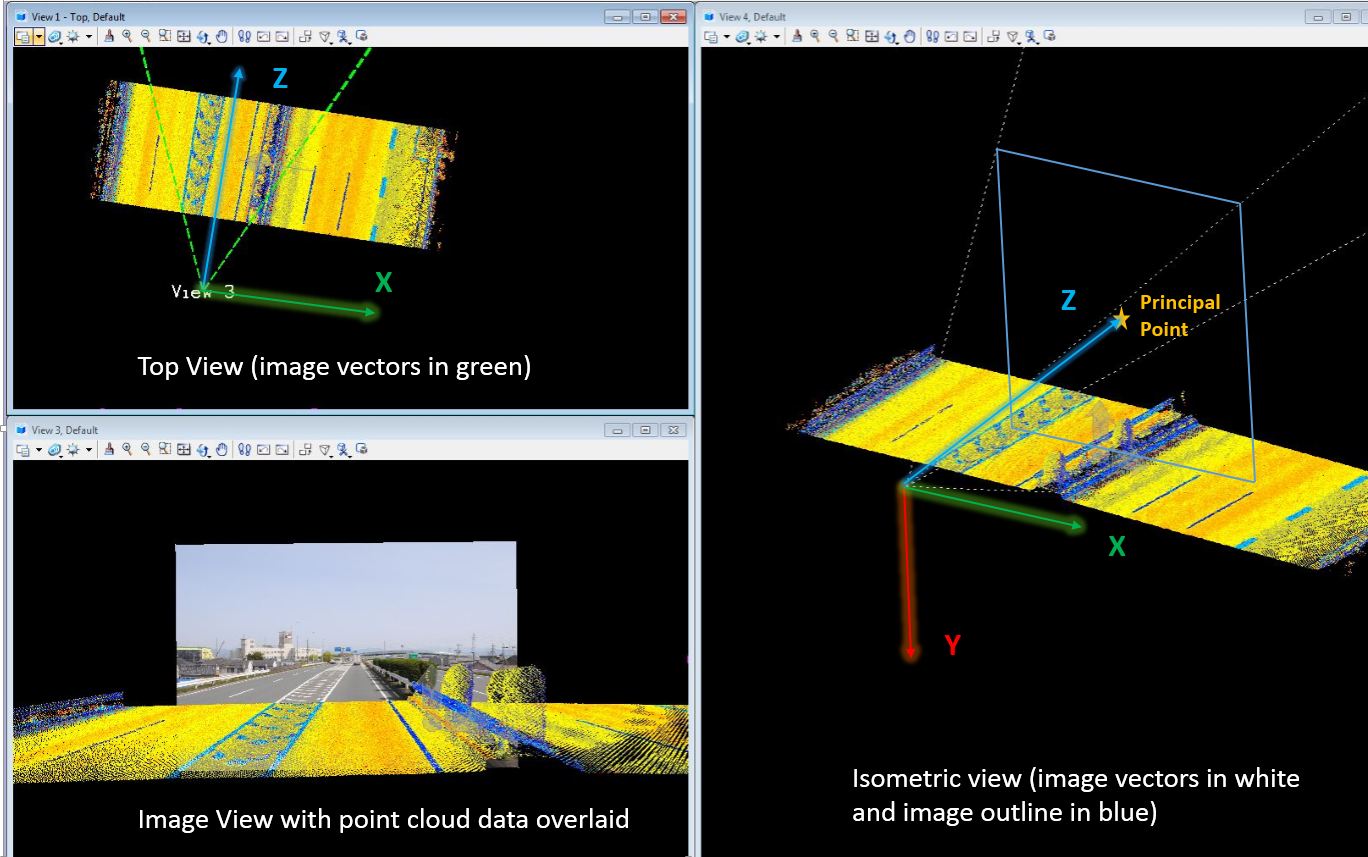
Camera – Index for the camera calibration to use for the image.
Requirements
Calibrated images combined with point cloud data greatly improve the productivity and quality of the extract process. Typically, a user simply clicks on a point and TopoDOT will search through thousands of images to quickly find the closest image and import it automatically. Once the image is loaded, the user is able to switch between cameras to view adjacent areas. TopoDOT® users continuously exploit the detail in high resolution calibrated images to identify features and assets within the point cloud. Thus maintaining an organized image project format is imperative for overall process performance.
In order to effectively identify and locate the images closest to the selected location, TopoDOT® places specific requirements on how the image project (*.iprj) should be exported.
- There should be only one camera calibration (*.cal) for each physical camera in an image project (*.iprj, *.lst). Failure to do so will result in users being unable to distinguish between the same cameras defined in other locations.
- Image list file (*.lst) should maintain the same file name as its parent image project file. This allows TopoDOT to automatically locate the image list file (*.lst) and not require an additional prompt from the user.
- All trackstrajectoriessetups should be exported into a single image project (*.iprj, *.lst) Failure to do so will require the user manually select each file. This can be a tedious process when many tracks are involved. This also complicates the TopoDOT® process for automatically reprojecting CAD elements to adjusted point clouds when using pre- and post-adjustment camera orientation files as the process input.
- In the event that separate image projects (*.iprj, *.lst) must be created and the camera calibrations (*.cal) have not changed, the camera calibration files should be recycled from the same location. Failure to do so will result in users being unable to distinguish between the same cameras in different trackstrajectories.
Example Image Project Directory Structure:
- Project
- FrontLeft.cal
- FrontRight.cal
- RearLeft.cal
- RearRight.cal
- Image Project.iprj
- Image Project.lst
- TrackA
- Jpegs
- TrackB
- Jpegs
- Track–
- Jpegs
- TrackA
*Note that bold labels are directory names
1 Comment
Balint Vanek · September 17, 2020 at 12:08 PM
It would be nice to know how these coordinate systems are defined, with respect to the photogrammetry PATB system (https://support.pix4d.com/hc/en-us/articles/202558969-Yaw-Pitch-Roll-and-Omega-Phi-Kappa-angles)
Here it seems like roll happens around the East-West axis and pitch around a North-South axis suggesting an East-North-Up (local) coordinate frame.